
Summary
- RFC 1315 defined managed objects for Frame Relay DTEs and modeled Frame Relay as one physical network interface with many virtual connections or neighbours.
- Its DLCMI objects define enquiry intervals, a count window and an unanswered-enquiry threshold that may declare the interface down; the MIB also holds separate circuit and error groups.
- A configured threshold, a state value or an interface-down declaration is evidence about that managed interface state. It does not prove that every virtual circuit, remote endpoint, packet stream or application result failed.
One attachment, several relationships
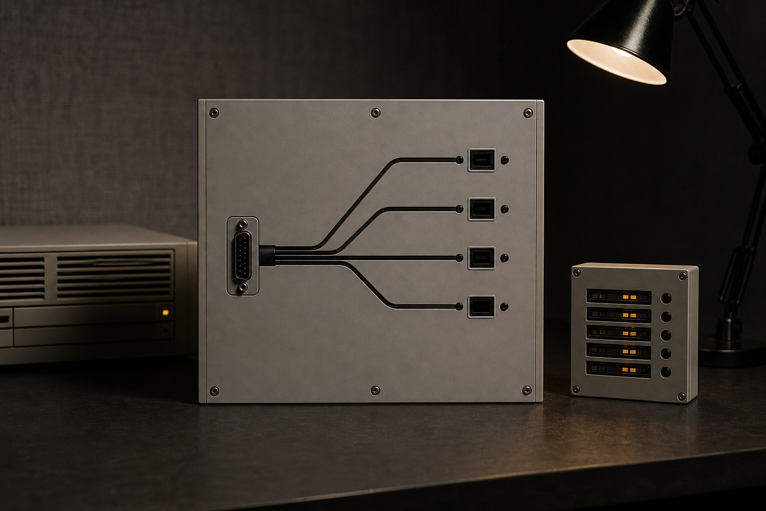
Frame Relay can make a physical attachment look simpler than the relationships carried over it. In RFC 1315’s operational model, the attachment is a single interface to a network. On the other side of that interface may be many destinations or neighbours reached through virtual connections. The RFC explicitly treats the medium as multi-access rather than as a collection of separate point-to-point physical connections.
That choice gave network management a useful hierarchy. A manager can group virtual connections with the physical connection to which they correspond. Troubleshooting becomes easier when circuit records do not float without the interface that carries their management relationship. But grouping is not fusion. The MIB still contains a DLCMI group, a circuit group and an error group because they answer different questions.
A circuit-table entry can describe a particular Data Link Connection Identifier and virtual circuit. An interface record can describe management parameters active at an interface. An error record can count a specified sort of observation. The reader should not let the shared physical attachment make one record a substitute for another. A circuit being represented in a table does not show that it passed traffic. A physical interface being declared down does not narrate what each virtual circuit did beforehand, afterward or elsewhere. A counter does not tell us which application was affected.
Turning silence into a local state
The DLCMI portion of RFC 1315 makes the boundary concrete. It defines a polling interval for successive status-enquiry messages and a full-enquiry interval. It defines an error threshold: the maximum number of unanswered status enquiries the equipment accepts before declaring the interface down. It also defines monitored events, the number of polling intervals over which that threshold is counted.
These fields are a design for bounded inference. The agent does not declare an interface down merely because it has one quiet moment. It counts a particular kind of missing management response inside a configured observation window, then applies a configured threshold. The resulting declaration has a precise scope: it is a local management judgement concerning that Frame Relay interface under those configured rules.
It is tempting to replace this with the sentence “the network was down.” RFC 1315 does not warrant that expansion. The MIB does not establish why responses were absent, whether a carrier failed, whether a remote device was unavailable, whether all virtual circuits had changed state, or whether a user-visible service was interrupted. It supplies an operational state model, not a retrospective universal cause.
The same care applies to frDlcmiState. The object states which data-link connection management scheme is active on the interface, and by implication which DLCI it uses. That is a configuration/state fact at the interface. It is not a portable identity for the full network, a certificate of a peer, or a live proof that every associated virtual circuit is usable. RFC 1293’s InARP article in this series concerns a different step: asking for a protocol address when a DLCI is already known. RFC 1294 concerns an explicit VC-to-encapsulation assignment and the interpretation of a frame label. RFC 1315 starts at neither of those places. It records how a manager organizes and judges a shared attachment.
Change is a thing to observe
RFC 1315 says that virtual circuits can be added, deleted and change availability during normal operation. The fact matters because it prevents a static inventory from becoming a health claim. A circuit list is a model that needs time. A row may be created, later removed or changed. A status observed on an interface may precede, follow or fail to coincide with a change in a particular circuit.
The MIB defines a Frame Relay trap intended as a corollary to the familiar SNMP Link Up and Link Down traps, because changes in virtual-circuit availability also interest the manager. A trap is a notification about a managed event. It is not an audit of every frame, a promise that a notification arrived, a proof that a downstream system consumed it, or an application outcome. Its value comes from retaining its event scope and correlating it with the appropriate interface and circuit records.
This distinction is especially helpful during incident reconstruction. An operator may have a local state transition, an inquiry counter, a circuit-table snapshot, a trap, a configuration history and traffic measurements. They should remain separate evidence. The state transition says what the management agent decided. The counter says what it counted. The circuit row says what the MIB represented. A packet capture or a service probe, if one exists, says something else. Connecting the records can produce a diagnosis; replacing them with one another produces a story too certain for its evidence.
A MIB is a map of questions
The Network Management Framework described in the RFC gives each object a name, syntax and encoding. This is more than cataloguing. It makes the management questions addressable. An object type and an instance identify a particular managed instantiation; that does not make the object a complete description of the physical world.
RFC 1315’s interface/circuit/error arrangement is therefore a useful historical lesson in observability. One layer can offer a compact state judgement while another retains per-circuit records. The manager benefits from grouping virtual connections under a shared attachment, but must retain the boundary if a local interface signal is later used to explain a circuit or service claim.
The common failure is not counting too little. It is allowing an easily collected counter to become evidence of everything adjacent to it. A threshold can be correctly configured and still not settle the remote cause. A circuit counter can move and still not identify a user action. A trap can be emitted and still not prove receipt. RFC 1315 built an object model that makes these distinctions available; responsible interpretation keeps them there.
What the declaration can say
An RFC 1315-compatible management record can support narrow statements: an agent had a specified DLCMI configuration; it used a specified polling interval and count window; it observed enough unanswered enquiries under that configuration to declare an interface down; a circuit entry or a trap existed at a particular management time. With other independent evidence, an operator can ask additional questions about circuits, remote endpoints, traffic or applications.
Those questions cannot be answered by promoting the interface declaration. A physical interface is a shared surface. Virtual connections are different managed relationships on it. The careful diagnosis is not weaker for saying so. It is the only diagnosis that leaves room for evidence from the circuits and services that the shared surface does not itself describe.
Sources and evidence limits
This article relies on RFC 1315, Management Information Base for Frame Relay DTEs (April 1992). It supports the MIB’s Frame Relay physical-interface/multiple-virtual-connection model, its DLCMI/circuit/error groups, polling and full-enquiry intervals, threshold/window objects, circuit availability changes and the corollary trap. It does not establish any live interface, carrier, remote peer, circuit outage, packet event, customer effect, repair or restoration.
Member Briefing
Deeper Profile Context
Sign in with the right membership level to unlock the full briefing and source notes.
Only for Strategic Circle
Strategic Circle
Open to all readers. Unlock profile briefings after joining and signing in.
Join Strategic CircleOnly for Leadership Alliance
Leadership Alliance
For qualified IP-asset owners and management; sign in to unlock alliance briefings.
Join Leadership Alliance